
ANALYSIS
The different types of analysis that will be performed will be mechanics of materials, statics, and mechanical design. There would be an analysis of the torsional stress generated in the shafts of the crushing wheels. There would be an analysis of the gear ratio required to help meet the 2500 lb-ft of torque. Torque equations will also be utilized for their relation to rpm. The knoleged gained from these analysis will help the system be as efficient as required
Analysis 1 - Max Motor Torque

Analysis 1 is to calculate the maximum amount of torque produced when the motor is operating at 100%. Using the equation T=63000 P / n, where T = torque (lb-in), P=hp (hp = 550 ft-lb/s), and n = rotational speed (rpm). This equation can be found in Mott chapter 3, equation 3-6.
Analysis 2 - Sprocket Gear Reduction Ratio

Analysis 2 Gear Reduction Ratio, Sprocket is to calculate the appropriate gear ratio to provide 2500 lb – ft into the crushing wheels. This was achieved using relationships with Mott’s equations for Torque-Power-rpm and train value.
Analysis 3 - Torque Output
Analysis 3 Torque output was calculated at the end of each gearbox at max output. The first gearbox has a ratio of 20/1. While the motor is at a max output of 5 hp @1750 rpm, the output of gearbox 1 is 300 lb – ft. The second gearbox has a ratio of 15/1. While the motor is at max output, the output of gearbox 2 is 4500 lb – ft. The max torque output at the crushing wheel was calculated to 12600 lb – ft.

Analysis 4 - Pulley Tension
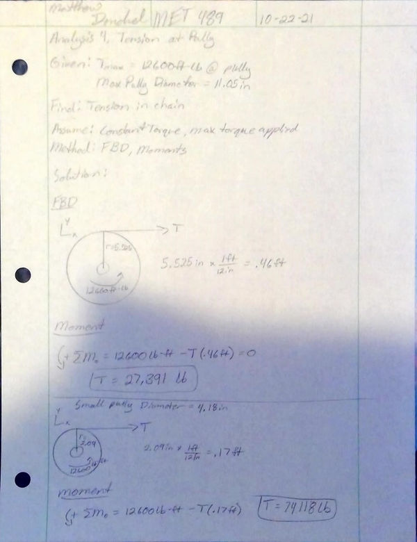
Analysis 4 The max tension generated in the chain was calculated to be 74118 lbs. This was accomplished by calculating the moment at the edge of each sprocket. With this calculation, the chain will need to accommodate a proper factor of safety.
Analysis 5 - Center Distance, Chain Length. and Design Power
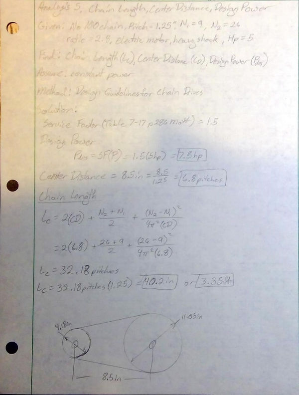
Analysis 5 The design power, center distance of the sprocket gears, and the chain length were calculated to gather necessary information for assembly. The design power was calculated with a service factor of 1.5. This was obtained with the given information of being an electric motor undergoing heavy shock. The design power was calculated to be 7.5 horsepower. The center distance was measured from the existing assembly to be 8.5 inches or 6.8 pitches. The chain length was calculated to be 40.2 inches or 3.35 feet. This is the minimum length of chain required for these sprocket gears and their current orientation.
Analysis 6 - Chain Pin Shear Stress

Analysis 6 The shear in the pin was calculated to check if the pins would be able to sustain max amount of tension calculated from analysis 4. The pins on the roller chain are in double shear. With this information max shear calculated in the pin was 127 ksi.
Analysis 7 - Shear Force to Crush Carbon Fiber

Analysis 7 The shear force to delaminate the carbon fiber strip was calculated to give a value key for Analysis 8. The given information of 12500 psi of yielding stress was obtained from Matweb.com for an adequate stress value for delamination.
Analysis 8 - Torque to Rotate Crushing Wheel

Analysis 8 The torque required to rotate the crushing wheels was calculated to be 2114 lb-ft. This calculation confirms the improvement of 2500 ft-lb in torque is adequate for the delamination of the carbon fiber strips.
Analysis 9 - Spur Gear Analysis

Analysis 9 The spur gear analysis performed on a provided spur gear analysis spreadsheet. The analysis was done with a diametral pitch of 5 and number of teeth of 40 to keep pitch diameter and center distance the same. This information was done to keep the diameter and center distance the same as current shaft setup. This analysis was based off the previous analysis of the spur gears. The analysis calculated a bending stress of 172 ksi and a pitting stress of 109 ksi. Using figure 9-19 in Mott, the minimum Brinell Hardness level will approximately be 230. Using this information one possible material spec can be specified as SAE 1340 OQT 700. SAE 1340 OQT 700 has a yield strength of 197 ksi and a Brinell Hardness of 444.
Analysis 10 - Actual Horsepower Required
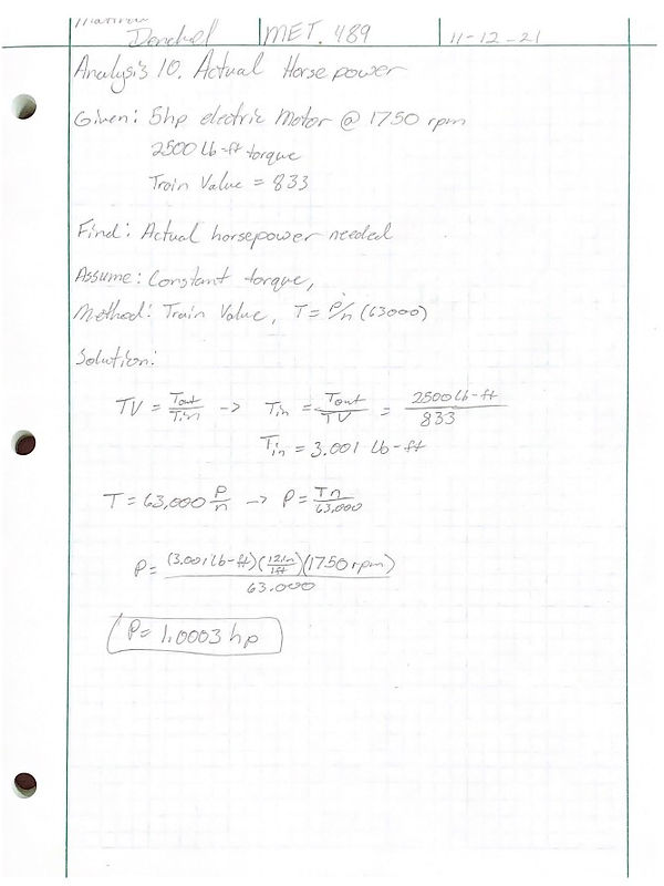
Analysis 10 This analysis was to calculate the actual needed horsepower required to delaminate the carbon fiber strips. The actual needed horsepower was calculated to be 1 horsepower to delaminate the carbon fiber. This information will help in the spur gear analysis from analysis 9.
Analysis 11 - .313in Square Key

Analysis 11 This analysis was to calculated the material required for the keystock to be manufactured with. This was assuming the keystock was 2 inches in length and fit in the standard size keyway in the gears. This analysis was performed for a .313 inch square keyway. It was calculated that only a select materials would have the yield strength capable of handing the torque listed in the Mechanical Design text book.
Analysis 12 - .5in Square Key
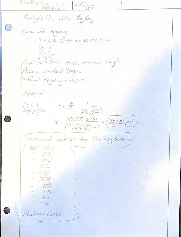
Analysis 12 (Appendix A-12) This analysis was to calculated the material required for the keystock to be manufactured with. This was assuming the keystock was 2 inches in length and fit the standard keyway in the gears. This analysis was performed for a .5 inch square keyway in the gears. It was calculated that a large variety of carbon steel and steel alloy materials would have the yield strength capable of handling the torque listed in the Mechanical Design text book.